
Cold start, gear house
Picture a cold start in a gear house. A creamy band fills the top of the sight glass, and someone asks for a can of antifoam. Two hours later, the band has gone. The glass looks clear. The pump gauge is still twitching.
Last week's particle count has jumped two codes, and the breather has been weeping a thin film down the tank all week. Nobody has asked where the air gets in, or whether the oil has changed. Those are two different questions, and the sight glass answers neither. The antifoam can wait until both have been asked.
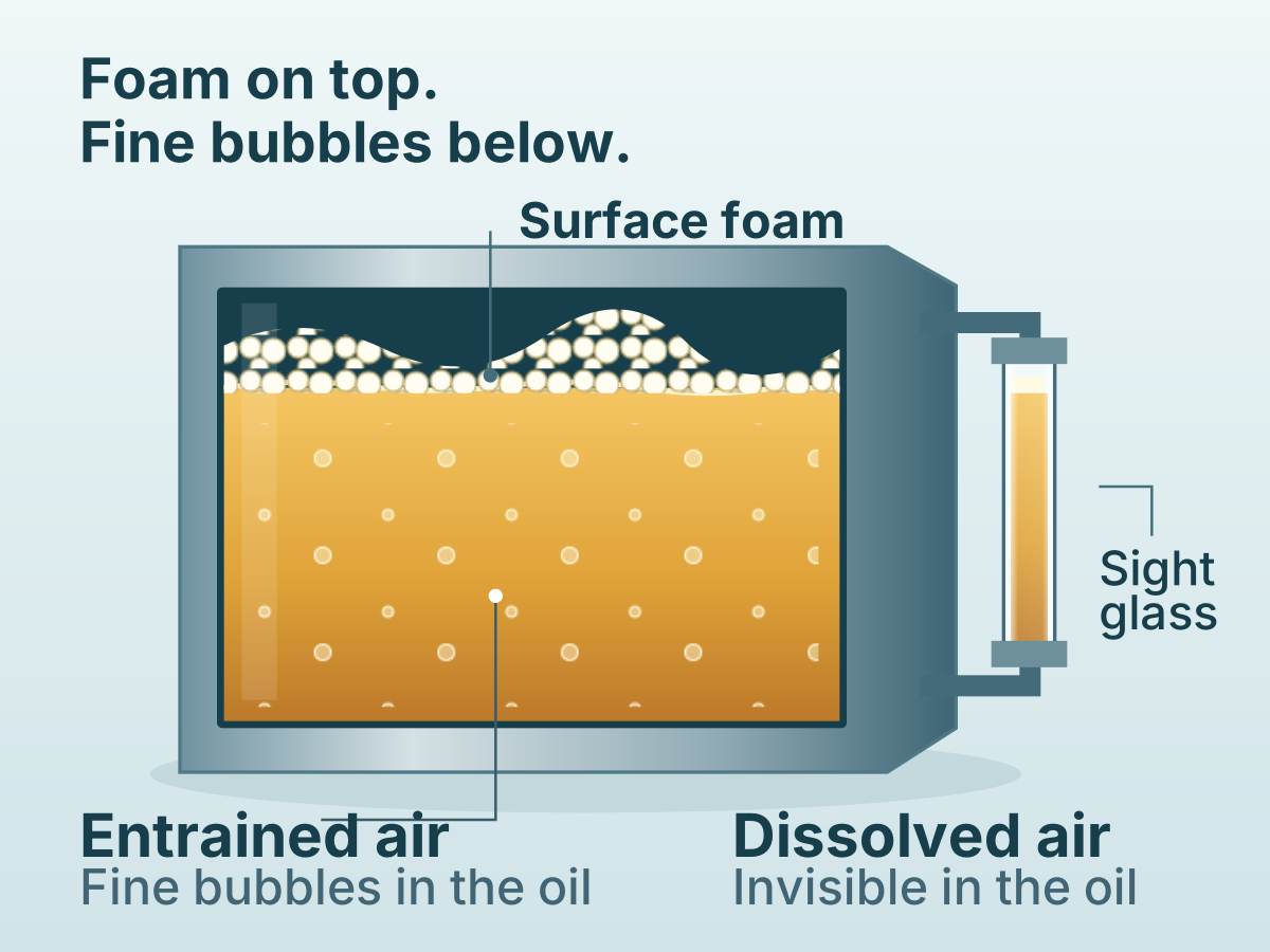
Air is in that oil three ways. Dissolved, it is invisible, though a mineral hydraulic fluid can hold up to 9 percent by volume of it at atmospheric pressure. Entrained, it is fine bubbles, cloudy when there are enough of them. Foam is the fraction that reached the surface and stayed.
Foam is only the air you can see. The pump, the bearings and the particle counter deal with the air you cannot.
Before the antifoam
Four things to settle before anyone opens the can
- Hold
No antifoam, and no top-up against a foaming glass.
- Time
Watch the foam and the haze separately as the oil stands.
- Walk
Find where air gets in.
- Test
Ask the laboratory whether the oil has changed.
In this article
Why the fine bubbles stay
Whether a bubble reaches the surface before the oil reaches the suction depends on how fast it rises and how long it has. For a fine bubble, rise speed goes with the square of its diameter and inversely with the oil's viscosity. Halve the diameter and it rises four times slower; cool the oil and it slows again.
A typical ISO VG 320 gear oil sheet lists 320 mm²/s at 40 °C and 25 at 100 °C. The ASTM D341 viscosity and temperature relation carries that to near 1,300 mm²/s at 20 °C and near 110 at 60 °C.
Treat the bubble as a rigid sphere, and the arithmetic is short: a 0.5 mm bubble climbs about 30 mm in five minutes at 20 °C, and about 370 mm at 60 °C.
The same arithmetic explains the morning. Oil tends to foam when it is cold, and cold oil holds its fine air longest. As the tank warms, the large bubbles leave, the surface layer collapses and the glass clears. The fine fraction lingers, and while the machine runs, every pass through the gears, pump and return line can make more.
Five minutes in the tank
Now give it the time a tank gives it. A 200 litre console tank circulating 40 litres a minute turns over every five minutes, and at 40 °C a 0.2 mm bubble in the gear oil needs more than an hour to rise 300 mm from return to suction.
So it goes round again, and the air release standard spells out what that can do: oil pressure that cannot be held and incomplete films in bearings and gears. That is the twitching needle.
A tank pass is not long enough for every bubble
Large bubbles rise quickly. Fine bubbles can return to the pump before they reach the surface.
Sources: Q8 Goya 320 and Q8 Henry 46 data sheets (typical values); ASTM D341.
- about 1 mm
- how far a 0.1 mm bubble climbs in five minutes in ISO VG 320 gear oil at 20 °C
- about 15 mm
- the same bubble in the same oil at 60 °C
One five-minute pass clears nothing much under half a millimetre, even from warm gear oil. A typical ISO VG 46 hydraulic oil does no better at 20 °C, and at 60 °C it still keeps everything under about 0.2 mm.
Where the air gets in
Usually it is the machine. Air typically enters a hydraulic circuit through the suction line when seals and fittings are not tight. The suction side runs below atmospheric pressure, so a loose joint there pulls air in without letting oil out; it stays dry and nobody sees it.
Returns and drains that end above the oil beat air in with every litre. One pump maker's reservoir guidance asks for drain and bleed lines ending at about half the fluid level, the suction inlet at least eight pipe diameters below the surface, and baffles that give the bubbles time to rise.
Trace the air back to its entry point
A dry suction joint can still draw air in. A return above the oil can beat air into it.
Level and cold starts decide where the foam goes. A sump filled to the top of the glass leaves the foam nowhere to go but the breather. One gear maker's fault table files oil at the breather under frequent cold starts or a high oil level, and the remedy it lists is mechanical: an expansion tank.
The oil can change too. In Flender's trend table, cloudy oil points to water or other foreign fluids, and a falling silicon value to an anti-foaming additive used up. The same manual forbids mixing oil types or makers. Each is a question for the laboratory.
Air corrupts two readings you already trust
The level. Flender's manual allows it to be read only at standstill, with the oil foam-free, after 5 to 10 minutes shut down. The rule is not fussiness: a foaming glass gives a false level, and a top-up made against it can overfill the sump, which feeds the breather and the foam in turn.
The particle count. The same manual has the laboratory thin the sample so that no air bubbles are counted. A light-extinction counter registers whatever blocks its beam, and the counting method, ISO 11500, is written for single-phase liquids; a bubble is a second phase. Before a jumped cleanliness code sends a filter cart out, ask whether that sample was degassed.
At the next stop, with a stopwatch
At the next planned stop, with the machine isolated under the site procedure, collect five things.
- The sample, taken running before the stop or within the manual's window after it, with the new-oil reference, noting that the oil was aerated.
- Oil temperature at the stop.
- Foam band height and the haze below it at the stop, then at 1, 5 and 10 minutes.
- Standstill level at 10 minutes, logged with the temperature.
- Every return and drain against that level, the baffle, the suction depth and any disturbed suction joint.
Foam that collapses within minutes while the haze stays tells you the fine fraction is large. Trust the level only against the mark and the last standstill reading. A level taken while running carries the air and, on a circulating system, misses the oil still out in the lines.
Two tests, two questions
Foam and air release are separate properties, and a good result on one says nothing about the other. ASTM D892 blows air through the oil at 24 °C and 93.5 °C and rates the foam it builds and the foam left after settling. ASTM D3427 times how long entrained air takes to fall to 0.2 percent by volume.
Two tests answer different questions
One measures foam at the surface. The other times how quickly air leaves the oil.
Some data sheets carry only one: the gear oil sheet above lists foam figures and no air release line at all. The air release method may not rank oils where residence times are short and gas contents high, so read both results as a change against the new-oil reference, not as a pass mark.
Ask for both, with the test temperature on the report, plus viscosity at 40 °C against the nominal grade, water by Karl Fischer and the element trend, silicon included.
Air path or changed oil
| What you see | What it may mean | Next step |
|---|---|---|
| Foam gone in minutes, haze stays | A large fine fraction | Walk the tank; compare air release with the reference |
| Haze after hours of warm standstill | Water or another fluid, not only air | Water by Karl Fischer |
| Standstill level above the mark | Water or another liquid, or a top-up against foam | Last standstill reading; water test |
| Oil at the breather after cold starts | A high level, or cold foam | Level at standstill; an expansion tank |
| Particle count up on an aerated sample | Bubbles counted as particles | Ask whether it was degassed; resample |
| Foam or air release off the reference | Water, a mixed product or a depleted additive | Find the cause; the oil's maker decides usability |
If foam and air release match the new-oil reference, the oil's air handling has not changed, and the air path you found on the walk is the job.
The creamy band was the easy part. The air that never reached the surface is what the pump has been running on since the cold start, and a stopwatch at the next shutdown will tell you more about it than another can of additive.
Primary references
- Flender GmbH, Assembly and operating instructions 7300en: Gear unit lubrication and gear unit preservation, version 07/2026, pp. 21, 23, 47 to 48, 50, 52 and 54.
- SEW-EURODRIVE, X..e series helical and bevel-helical gear units: Possible malfunctions/remedy, edition 04/2026.
- HAWE Hydraulik, B 7960, Operation instructions for axial piston variable displacement pumps type V30D, January 2001, pp. 2 to 3.
- Danfoss Power Solutions, Technical Information 520L0463, Hydraulic Fluids and Lubricants, July 2016, p. 10.
- ASTM International, D892-25, Standard Test Method for Foaming Characteristics of Lubricating Oils, scope and significance.
- ASTM International, D3427-26, Standard Test Method for Air Release Properties of Hydrocarbon Based Oils, scope and significance.
- ASTM International, D341-20(2025), Standard Practice for Viscosity-Temperature Equations and Charts for Liquid Petroleum or Hydrocarbon Products, scope.
- ISO, ISO 6247:1998, Petroleum products: Determination of foaming characteristics of lubricating oils.
- ISO, ISO 9120:1997, Petroleum and related products: Determination of air-release properties of steam turbine and other oils, Impinger method.
- ISO, ISO 11500:2022, Hydraulic fluid power: Determination of the particulate contamination level of a liquid sample by automatic particle counting using the light-extinction principle.
- Q8Oils, Q8 Goya 320 product data sheet, typical values.
- Q8Oils, Q8 Henry 46 product data sheet, typical values.
- NPTEL, Viscous Incompressible Flows, lecture 27: Low Reynolds number flow around a sphere.